You have a piece of Cibatool material which is 100 x 60 x 25 mm. Within these limits you can design the part the way you want it. Make sure you leave minimum 5 mm to clamp in the bottom.
To keep things simple, you only have one flat end mill available, thus limiting the level of detail of your part. The specifications are:
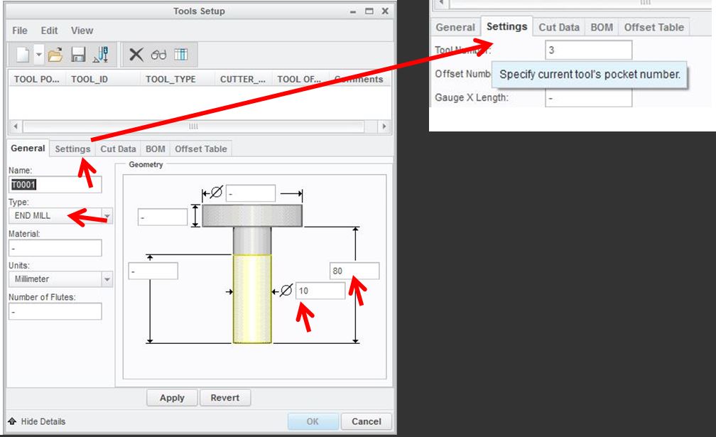
Diameter: 10 mm
Length: 80 mm
Number of teeth: 2
A) The
Manufacturing Model is defined by:
-
assembling the design model (part to be produced,
also called reference model)
- With
a workpiece (representing a raw piece of material)
and
- With
a milling volume (representing the volume where the
tool is 'allowed' to move around in)
B) The
Manufacturing is set up. You define:
- The
type of machine that will be used (tools can also be
defined at this point)
- The machining coordinate system
C) The
Machining NC Sequences are defined:
-The
tools,
-The
retract plane (datum plane/surface where tool can
move rapidly without collision with the workpiece)
-Tool
motion parameters and the material to be removed are
defined.
-The
operation is saved
A):(Reference
model , workpiece & milling volume)
1)Make sure
your working directory is OK
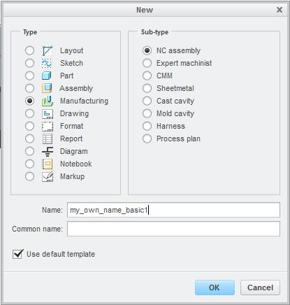
2) Create a new file with settings shown right. Verify you use mm. The file will have an .asm extension.
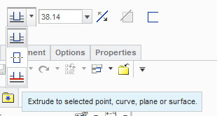
Extrude the workpiece to the same height (Depth Value, here max. 25 mm) as the reference model.
Use Extrude
To selected and pick any top point on your
reference model.This ensures that
the workpiece gets the same height as your reference model
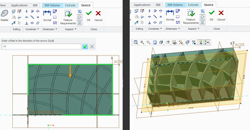
1) Extrude...MILL VOLUME
and
2) Trim
id...MILL VOLUME
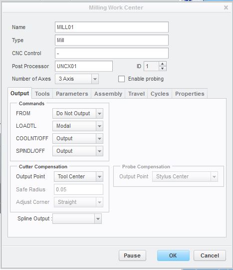
1) On the Manufacturing pane, click Work Center / Mill and in the Milling Work Center box click the OK button for closing the box again (Nothing changed...), thus preparing the system for a 3 -Axis milling session (default setup...).
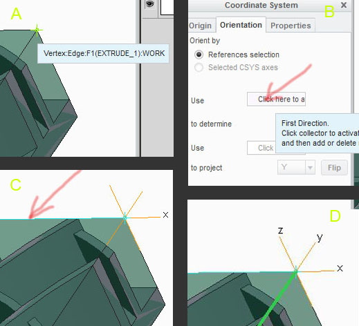
In the box, jump to the Orientation pane and activate the area with the red arrow (pict. B).
Click on the top horizontal edge to define the X axis (pict. C).
still on the Orientation pane, repeat the above actions to define the Y axis by activating the lower Click here to... button. Use one of the Flip buttons to ensure that the Z axis points upwards - This is imperative! The X and Y axes must be orientated as shown (pict. D).
Close the Coordinate System box with an OK. On the top ribbon click the blue Resume button followed by the green acceptance button. Verify that Datum display is turned ON.
1) Go to the Mill pane and choose Roughing / Volume Rough. The Volume Milling pane will appear on the ribbon and needs input values for Tool, Reference, Parameters and Clearance.
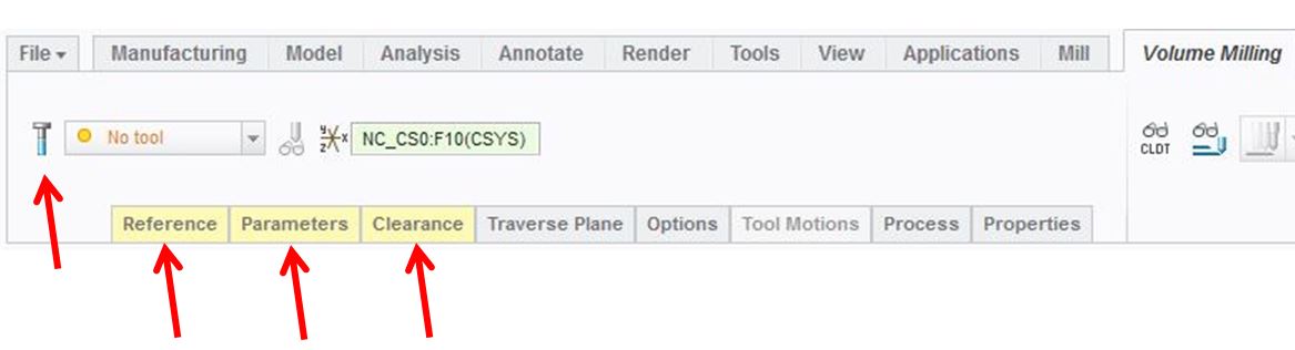
2) Click on
the Tool
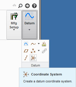
icon: the Tools Setup box appears. Here and
END MILL tool with a length of 80 mm
and diameter of 10 mm has to be defined.
Enter the Settings
pane and set 1 as
Tool number. Apply and close box.
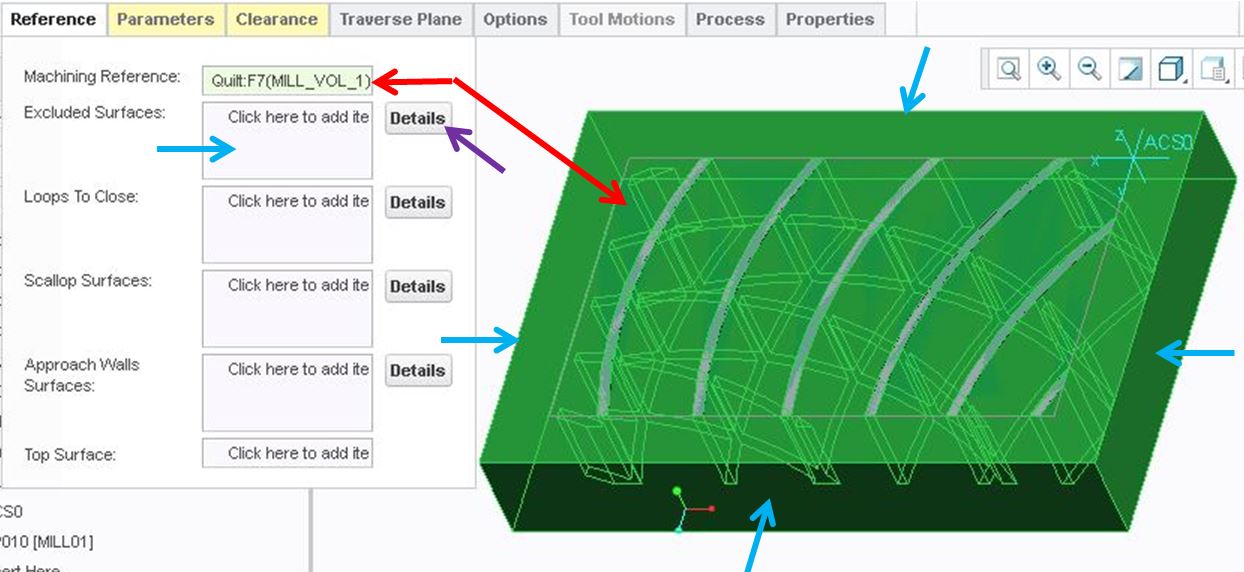
3) Choose
the Reference
pane,
and when asked for Machining
Reference, (what to remove by the milling) click on the
Milling volume. (Red
arrows)
To
save time in the toolshop
session, click in the Excluded
Surfaces field
(surfaces to
exclude from profiling) and select
then (using
ctrl) the four vertical walls on
the Milling volume(Cyan arrows).
Use the
Details
button to check that all four are chosen.
This will reduce the time spent on "machining air"
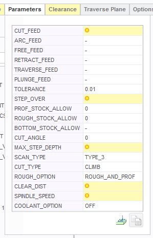
4) Choose
the Parameters pane.
The precolored areas are to be defined:
CUT_FEED = 75,
STEP_OVER = 5,
MAX_STEP_DEPTH = 2.5,
CLEAR _DIST = 2 and SPINDLE_SPEED = 500.
Additionally, set ROUGH OPTION to ROUGH_AND_PROFILE.
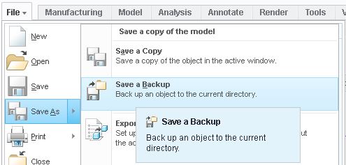
Choose File / Save As / Save a Backup to a suitable destination - Preferably a USB drive. The Save a Backup will generate 4 - 5 files. Use the Organize / New Folder option to keep the files together - they will all be used in the milling process.