|
1.
INSPECTING THE MODEL
To start
with I look at the model to find problem areas and to get a general overview
of the model. I look for:
- parallel
sides that could be used for clamping
- internal
corners that should be (if possible!) sharp
- rounds
and other surfaces that are not parallel or normal to any of the major
planes (xy, zx & zy). These will require surface milling with a
ball mill
- areas,
where uniform machining (same tool/same approach would be desirable
or most logical
|
| TOP:
Check
space and radius of rounds |
FRONT:
Small
space between front light and bumper |
| BACK:
Small
space between axle and flat bottom |
BOTTOM:
Small
space behind wheel |
| SIDE:
Small
space around wheel |
|
|
|
2.
PLANNING CLAMPING/OPERATIONS
The main
focus is on making clamping of the truck possible after each operation,
and to decide what to machine from where; there is always more than one
solution.
One way
to confront the clamping problem is to think forward to the last operation:
How will you clamp the truck when almost all of it is machined? What should
be the last operation? You need to have parallel planes/surfaces available.
In this case,
there are parallel planes available on the sides and the wheels. For a
last operation, either will do fine.
When placing
the Reference Machining Zero coordinate system, already machined surfaces
are optimal as references. This is utilized from Operation 3 onwards.
|
Chosen sequence
of operations (shown here with fixture suggestions):
|
OPERATION
1
Machining of the right side. The Reference Machine Zero, RMZ is
on top of the work piece, centered in x and y.
|
OPERATION
2
Machining of the left side. The location of the RMZ is the same
as on the right side, opposite side of workpiece of course
|
|
OPERATION
3
Machining of the bottom. The RMZ is on the bottom of the truck,
centered in x and y.
|
OPERATION
4
Machining license plate area in the back. The RMZ is on top of the
work piece, x is located on the bottom face of the truck
|
|
OPERATION
5
Machining the front. The RMZ is on top of the work piece, x is located
on the bottom face of the truck
|
OPERATION
6
Machining the rest from the top. The RMZ is on top of the work piece,
x and y is centered according to already machined surfaces on the
truck.
|
|
|
3.
STARTING A NEW MFG SESSION
OPERATION 1
The actual
CAM work starts. You retrieve the truck, create the workpiece and set
up the first operation, including fixture.
While it
is not absolutely necessary, it is a good idea to visualize the fixture.
It makes it easy to discuss this with the operator. Furthermore, you can
check whether there will be collision with the tool when doing the NC
Checks.
|
Click the
buttons to set up the fixture. The fixture will be a part on its own.
When sketching, reference the sides of the workpiece. If this changes,
the fixture will too.
|
|
4.
CREATING SEQUENCES
Take a look
at the NC Check video first. Underneath is described the sequences in
this operation.
Parameters
different from the default milling parameters are listed.
| OPERATION
1 |
| Sequence
1 - Volume Milling - 10 mm end mill |
| |
Parameters:
Scantype = type_spiral
Rough_option = rough_&_prof |
| Sequence
2 - Surface Milling - 4 mm ball mill |
| |
Window
finishing
Parameters:
Scallop_hght = 0.02
Lace_option = Line_connect
More
on these two important parameters below
|
| Sequence
3 - Surface Milling - 4 mm ball mill |
| |
back
wheel, cutline surface milling in a helical movement.
Parameters:
Scallop_hght = 0.02
Scan_type = type_helical |
| Sequence
4 - Surface Milling - 4 mm ball mill |
| |
front
wheel, same as Seq. 3 |
| Sequence
5 - Volume Milling - 2 mm end mill |
| |
Volume
above the wheels
Parameters:
Scantype = type_spiral
Rough_option = rough_&_prof |
|
WATCH VIDEO of OPERATION 1
|
1st
volume (seq. 1) shown in red
2nd
volume (seq. 5) shown in red
|
Notes:
The volume milling sequence (no. 1) removes material on the
sides and partly around the wheels. Surfaces parallel
or normal to the retract plane are finished (machined
to the measure). The volume, and therefore the milling, stops
at the backside of the wheels, as it is not machinable within
the current operation.
Notice that the volume extends beyond the boundaries of the
workpiece in the xy plane, to make sure the workpiece is completely
removed.
Rule of Thumb: This distance should be Tool diameter
+ 1
To make room for a surface finish of the window, this area is
included in the volume.
For
Operation 3 we need to clamp the truck with the bottom up, therefore
the workpiece is not machined in its entire width, see clamping
for Operation 3
The
second volume milling sequence (seq. 5) removes the material
above the wheels, where the bigger tools could not go. A new
volume is created for this sequence.
There is not much room here, so a 2 mm mill is the only choice.
Because of its limited length, the volume is no deeper than
the tool is capable of.
The remaining material can be further reduced in another
operation, but not entirely, and there will be difficulties
with strange tool overlaps. In
other words, and in this particular case - it is not worth while.
The
surface machining of the window includes the border around it.
There is also a compromise here: the sharp corners could be
better if a small end mill, a flat mill, was used all over,
but because the window is not normal to the z-axis, it won't
be sufficient anyway.
Look
at the screenshots to the left. A 2 mm endmill takes a round
after the milling with the 4 mm ball mill. There is a difference,
but it is not worth the trouble. It mainly creates new odd looking
surface details, because of the overlap between two geometrically
different tools
(screenshots
taken after completion of the whole truck, for clarity)
|
|
|
IMPORTANT
SURFACING PARAMETERS
In the first
operation, in the surface sequences, two very important parameters were
set. These two are not default:
- SCALLOP_HEIGHT
- LACE_OPTION
To the right
is an explanation of both of them.
In your final
assignment, always use:
SCALLOP_HEIGHT
= 0.02
LACE_OPTION
= ARC / LINE CONNECT
|
SCALLOP_HEIGHT
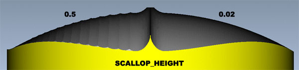
 Scallop height determines the roughness of the surface. Smaller values
pull the toolpath closer together, making the overlap bigger and produces
a smoother surface. At the cost of time of course.
Scallop height determines the roughness of the surface. Smaller values
pull the toolpath closer together, making the overlap bigger and produces
a smoother surface. At the cost of time of course.
LACE_OPTION
|
|

|
In surface
milling, the tool can either mill in one direction or in zigzag moves,
connected with straight lines or arcs.
Zigzag
is fastest, with as few retracts as possible, while answering NO makes
the tool retract after each pass, starting from the same side every
time. See animations to the right. |
|
|
5. CREATING
A NEW OPERATION
OPERATION 2
To continue
the milling on the left side of the truck, a new operation is set up,
with the Reference Machine Zero placed as shown in Operation
2, i.e on the opposite side of the workpiece.
The
milling sequences should be identical to those on the right side.
Volumes and
parameters can be copied from earlier operations/sequences. As the two
sides are identical, this makes sense. See
the menus to the right.
Watch the
machining of the left side by clicking on the movie.
|
|
|
6. BOTTOM
SIDE OF TRUCK
OPERATION 3
The engraving
- sequence 3 - is not included in the video.
Parameters
different from the default milling parameters are listed.
| OPERATION
3 |
| Sequence
1 - Volume Milling - 10 mm end mill |
| |
Parameters:
Scantype = type_spiral
Rough_option = rough_&_prof |
| Sequence
2 - Surface Milling - 4 mm ball mill |
| |
|
| Sequence
3 - Engraving - 4 mm ball mill |
| |
Name
of creator
Parameters:
Groove_depth = 0.1 and 0.3 |
|
WATCH
VIDEO of OPERATION 3
|
|
Notes:
To machine the bottom in seq. 1, a volume is ceated that extends
well beyond the boundaries of the workpiece, to make sure all
of it is removed. The volume stops at the bottom of the truck.
 In
the video you may notice that the tool enters the volume from
the side, instead of starting from the center. In
the video you may notice that the tool enters the volume from
the side, instead of starting from the center.
Entering side-ways is the best, and is always possible when
the volume is bigger than the workpiece, like in the picture
to the left. Some tool types can't drill - they have to enter
the workpiece horisontally.
See the menu to he right: Check Appr Walls and select the outer
vertical surfaces of the volume - the tool will now enter through
these "walls".
The
big surfaces of the tires have already been milled in Operation
1 & 2, therefore only the rounds on the tires are milled,
together with the axles, see animation to the left.
|
|

|
Engraving
following cosmetic Groove curves is very useful for engraving
small details or text onto the part. With the milling parameter
Groove_depth you can raise or lower the tool to a
desired height. No groove_depth value will make the tool
tip follow the curve at curve height.
The Groove feature is created in part mode, not in manufacturing
mode. Insert - Cosmetic - Groove
In
the animation above, groove_depth is just 0.1, meaning the
4 mm ball mill is lowered 0.1 mm into the bottom of the
truck, merely scratching the surface.
In the animation below, the groove_depth is 0.3, making
the engraving more visible
|

|
|
|
7.
NC CHECK
There are
two possibilities you should know about in NC Check simulation.
- How to
save an NC Check to be used as a starting point for another NC Check
- How to
simulate several sequences or operations
|
 Saving
an NC Check Saving
an NC Check
Right after doing an NC Check, you can save the image, so you can
continue from that point in a later NC Check instead of starting from
scratch. Look at the image to the right: Save is only available after
NC Check, while restore is always available to retrieve a saved NC Check.
Save-Restore
was used in the videos of the six operations.
Simulate
several sequences or operations
When you want to do an NC Check of more than one sequence or operation,
the thing to do is to 'collect' a set of either sequences or operations
and save a CL (Cutter Location) file for this set.
Here is how
it is done:
- Select
CL Data - Output - Select Set - Create (name of set, accept default)
- (pick the sequences/operations to form the set) - select
the named set again - File - Done
- Play it:
CL Data - NC Check - Display - Filename (select file) - Run
|
|
8. LICENSE
PLATE, BACK END
OPERATION 4
Parameters
different from the default milling parameters are listed.
| OPERATION
4 |
| Sequence
1 - Volume Milling - 4 mm end mill |
| |
Definition
of volume: Window
Parameters:
Scantype = type_spiral
Rough_option = rough_&_prof |
| Sequence
2 - Surface Milling - 4 mm ball mill |
| |
Plate
finishing
Parameters:
Scallop_hght = 0.02
Lace_option = Line_connect
|
|
WATCH
VIDEO of OPERATION 4
|
|
Notes:
The first sequence is the volume milling. Here, the volume is
defined by a 2D sketch, called a Window.
The
simplest way to define geometry for a volume milling sequence
is by using a Mill Window, that is, by sketching or selecting
a closed contour in the retract plane. All surfaces visible
within the contour will be milled.
The
second sequence is surface milling, where the sides and bottom
of the cavity for the license plate are milled.
|
|
|
9. FRONT
END
OPERATION 5
Previous
sequences have already machined parts of the front. The focus now is on
finish machining the two large surfaces on the front and get nice sharp
edges wherever possible, to make the frontlights stand out.
The space is limited, so the 2 mm end mill will be used.
Parameters
different from the default milling parameters are listed.
| OPERATION
5 |
| Sequence
1 - Surface Milling - 4 mm end mill |
| |
Semi-finishing
of two front surfaces
Parameters:
Rough_Step_Depth = 3
Scallop_hght = 0.1
Prof_Stock_Allow = 0.1
Lace_option = Line_connect |
| Sequence
2 - Surface Milling - 2 mm end mill |
| |
Finishing
front surfaces
Parameters:
Scallop_hght = 0.02
Lace_option = Arc_connect
|
| Sequence
3 - Trajectory Milling - 2 mm end mill |
| |
Finishing
sharp edges
The
bottom edge of the frontlight is followed, and the cutting height
- the tip of the mill - is controlled by the angled, large surfaces:
|
|
WATCH
VIDEO of OPERATION 5
|
2
large surfaces
|
Notes:
Notice the parameters sequence 1. When you add a Rough Step
Depth, you will have more than one level of surface machining,
in this case there will be 3 mm between each level.
Because
the next tool is a 2 mm mill- a rather fragile tool - the semi-finishing
with the 4 mm end mill is necessary to clear the way first,
leaving only a small amount to be removed with the 2 mm end
mill.
|
 |
The finishing sequences on the front and around the frontlights
is done with the same tool, a 2 mm end mill.
Normally,
surface machining of surfaces not normal to the z-axis are milled
with ball mills, but here it would leave some strange looking
edges.
The
2 mm end mill is used here because I want to avoid the problem
of strange geometry around the frontlights.
Had
the area on the front of the truck been larger, I might have created
additional sequences to spare my 2 mm - it should never do too
much work.
In this case, and because of the angled, but flat front surfaces,
it is OK. Front surfaces with curvature would force me to use
a ball mill. The result from an end mill would not be tolerable.
The
top animation shows what happens when using a ball mill and then
an end mill
The
bottom animation shows the case of the truck, where the same endmill
has been used for both the surface machining and the trajectory
finishing of the frontlight sides.
The
"end mill/end mill" solution gets closer to the model
geometry
|
|
|
|
|
10. FROM
THE TOP
OPERATION 6
Take a look
at the NC Check video first. Underneath is described the sequences in
this operation.
Parameters
different from the default milling parameters are listed.
| OPERATION
6 |
| Sequence
1 - Volume Milling - 10 mm end mill |
| |
Parameters:
Scantype = type_spiral
Rough_option = rough_&_prof |
| Sequence
2 - Surface Milling - 10 mm ball mill |
| |
Finishing
Parameters:
Scallop_hght = 0.02
Lace_option = Line_connect
|
| Sequence
3 - Volume Milling - 4 mm end mill |
| |
Parameters:
Scantype = type_spiral
Rough_option = rough_only |
| Sequence
4 - Surface Milling - 4 mm ball mill |
| |
Finishing
of front window and storage compartment
Parameters:
Scallop_hght = 0.02
Lace_option = arc_connect |
|
WATCH
VIDEO of OPERATION 6
|
No
surfaces excluded from profiling
Several
surfaces excluded from profiling, fx. on the front and on the
motor helmet
|
Notes:
 At
this point I want to introduce a time saving feature. Not time
saving for the programmer, but in the workshop, milling the
part: Excluding surfaces from profiling (found on Seq
Setup menu, shown to the right) At
this point I want to introduce a time saving feature. Not time
saving for the programmer, but in the workshop, milling the
part: Excluding surfaces from profiling (found on Seq
Setup menu, shown to the right)
When
you do a volume milling sequence, with the parameter Rough_option
set to rough_&_profile it means that for each
machining level, there will be a profiling pass, meaning a finishing
pass on all surfaces of the volume. Most of the time, this is
OK, but on surfaces, where you plan to do a surface milling
sequence later, the profiling pass might leave small lines,
visible after the surface milling sequence, look at the two
pictures to the left.
They
are in theory non existing, but volume milling is a roughing
process, where the tool remove a great amount of material, causing
vibrations. These vibrations may lead to unstability, causing
the tool to go a little closer than it was meant to.
Another
thing is that profiling the outer surfaces of the volume is
a complete waste of time, because they lie beyond the workpiece
boundaries. It won't do any harm, but it takes extra time.
Look
at the image below, these vertical meshed surfaces of
the volume should be excluded from profiling.
|
|
|
|
|
Comments
to the storage compartment in the back of the truck:
After
the first volume milling sequence, a fairly large amount of material
is not milled away, because the 10 mm is too big. Therefore a
small volume is created, to be used in sequence 3 with a 4 mm
end mill.
The
'floor' is not milled in any of the volume sequences, because
a uniform machining with one tool type is desired. Because of
the corner radiuses on the floor of the storage compartment, the
only tool usable is the 4 mm ball mill. The 10 mm end mill would
avoid the rounds and create a step instead.
The
vertical sharp corners of the compartment are not vital for the
look of the truck, so no effort is made especially to make them
sharper, i.e by using a smaller tool.
|
End
of case study
|
 This case study will help you when you do your final assignment in CAM.
From the exercises you will know what fx. volume, profile and surface
milling is about, but when it is best to use which
method takes a lot of experience. Spend about 30 minutes to read
this study.
This case study will help you when you do your final assignment in CAM.
From the exercises you will know what fx. volume, profile and surface
milling is about, but when it is best to use which
method takes a lot of experience. Spend about 30 minutes to read
this study.