MANUFACTURING
SESSION OVERVIEW
The basic
3 steps
 A
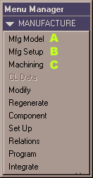
Pro/E Manufacturing session can be divided into 3 steps:
A) The Manufacturing Model is defined by assembling the design model (part to be produced, also called reference model) with a workpiece (råklods).
B) The Manufacturing is set up. You define:
- the type of machine that will be used (tools can also be defined at this point)
- the machining coordinate system
- the retract plane (datum plane/surface where tool can move rapidly without collision with the workpiece)
C) The Machining NC Sequences are defined. The tools, tool motion parameters and the material to be removed are defined.
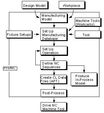
Chart from Pro/NC manual
We will look closer at these 3 steps
A) Manufacturing
Model
assembly of reference model with workpiece
1) Create new file
2) Assemble reference model
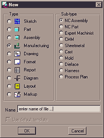 1)
Make sure your working directory is OK
2) Create
a new file with settings shown right. The file will have an .mfg
extension.
If you are prompted for a template to use, select mmns_mfg_milling.mfg
3) In the menus that have appeared, pick in sequence Mfg Model - Assemble - Ref Model.
4) Select your own pro/e part as the reference model, the part to be produced.
3) Workpiece creation
The next step is to define the workpiece, the part that represents the block of metal or plastic that we want to machine. This can be done either by assembling a predefined part or - as this example shows - by creation of the workpiece within the manufacturing session.
 1)
From the menu where you selected Assemble, select Create
to start the creation of a workpiece that refers to the assembled reference
part
2) Name the workpiece, fx. workpiece1.
3) Using
standard modelling techniques, create the workpiece as a solid protrusion.
If the workpiece should be the exact same size as the reference part,
the sketch plane can be selected from the reference part, like below.
Select Use Edge - Loop to reuse edges from the model
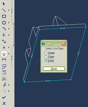
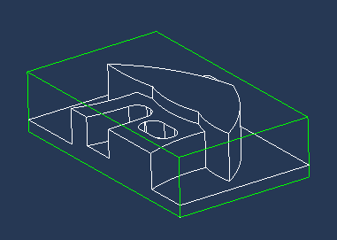
Workpiece in green, extruded to same height as reference
model
NOTICE: It is a good idea to select Use Edge when you are sketching, whenever this is possible. Doing that, you make sure that if the reference model changes, the workpiece or any other geometry created in a manufacturing session will change accordingly. Loop is the fastest and the easiest to use once you understand how it works. If you are not familiar with Use Edge, please read the following section!
Single / Chain / Loop
The Use Edge option in the Sketch menu creates Sketcher geometry by projecting selected model edges onto the sketching plane. There are three ways to use this option:
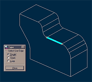 |
The Single method. You select individual lines from geometry previously created to project them onto the sketch plane. |
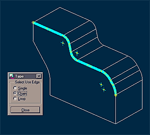 |
The Chain method. You select a chain of tangent lines from geometry previously created to project them onto the sketch plane. |
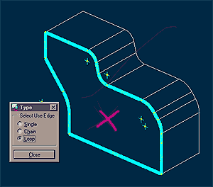 |
The Loop method. You select a surface from geometry previously created to project its edges onto the sketch plane. Do not pick any lines - pick the surface as in the illustration where the cross is. |
B) Manufacturing
setup
Operation setup
4) NC Machine
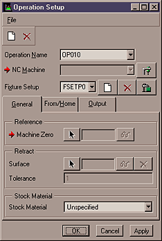 1)
Select Mfg Setup. The Operation Setup window appears, the red arrows
marking what has to be defined. You wil notice that Retract plane
is not absolutely necessary to define at this point, but we will do it
anyway. A reason for not defining a retract plane can be
if it will be different for each NC Sequence.
2) Click
on the icon for NC Machine ![]()
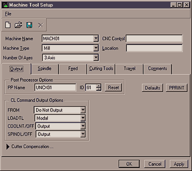
3) The Machine Tool Setup window is displayed. We will do 3-axis milling, so you do not have to make any changes to the default settings. They will work fine for our purposes.
It is possible to define the cutting tools to be used later, and the whole machine setup can be saved for future use.
 Without
a point of coordinate synchronization between what happens in Pro/E and
in reality - at the milling machine - the machining will not be successful.
That is why you have to define a Reference Machine Zero (a coordinate
system) - all coordinates are based on that coordinate system.
1) Select the Machine Zero arrow - select Create, since there is no suitable coordinate system (CSYS) we can use.
2) When asked in which model to create the CSYS, select the top assembly in the model tree. This makes it easy to find the coordinate system later, if we need to change it.
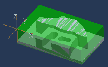
3) Create the CSYS at a corner of the workpiece like in the picture above. Hold Ctrl while you select the sides and the top of the workpiece (Origin settings), Orient the axes using these selected surfaces (Orientation settings).
It is not highly critical which way y and x axis are orientated, but the Z-axis must point upwards!
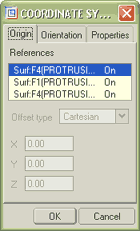
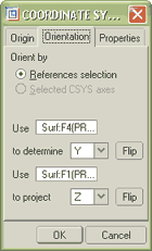
Origin and Orientation settings
6) Retract plane
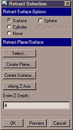 1)
Select the 'Select'-arrow for definition of a retract plane
2) Click Along Z Axis, set Z Depth to 4 mm
Between NC Sequences, the tool will move rapidly at a height of 4 mm above the Program Zero.
3) Accept the default tolerance
4) Select OK to close the Operation Setup dialog
C) CREATING NC SEQUENCES
- Do the sequence(s)
- Play Path with NC Check to verify that your sequence is OK
- Backup the files (see below)
- Go to the workshop, retrieve the files with FTP. The operator over there will know how
- Machine your part
Start a new NC Sequence of type Volume Milling
Follow the
COACH instruction to create the volume
necessary to machine your part.
Do
not pay attention to the parameters used in Coach, focus only
on how a volume is created and trimmed to the part. Offset the outer surfaces
of this volume by 11 mm to make sure the tool can go beyond the boundaries
of the workpiece.
It
is enough with one Volume milling sequence with Rough
Option set to Rough_&_Prof (roughing and profiling).
This is the only parameter you will have to change during setup of the
sequence.
View the 16 mins. video about this particular section of the work with your own part.
BACKING
UP FILES
From experience, we know that most students have a hard time finding their
files, when using another file browser than the one within Pro/E.
Where are my most recent files? Which files will I need in the workshop,
and how can I find them over there?
The solution is to backup your current manufacturing file/assembly
Select File
- Backup
In the Backup dialog box, navigate to a new directory or create one on-the-fly
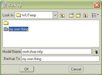
The
directory folder 'my own thing' selected as the backup folder.
The most recent files dependent
to the 'workshop.mfg' session are saved to this folder.
Note:
- Versions of the backup object are reset to 1 in the backup directory.
- If you back up an assembly, drawing, or manufacturing object, Pro/ENGINEER saves all its dependent files in the specified directory