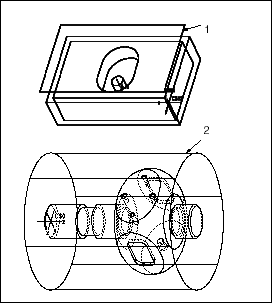
The retract surface defines the level to which the tool is retracted after a cut. Depending on your machining needs, you can specify the retract surface to be a plane, cylinder, sphere, or a custom-made surface.
You can specify the retract surface at the operation level, and then modify it at the NC sequence level, if needed.
When an operation Retract Surface is defined, the tool will traverse along this surface from the end of one sequence to the beginning of the next sequence.
The retract surface setting is modal, that is, once specified, it will stay for all subsequent NC sequences until you change it, as long as it is applicable to the NC sequence type. For example, if you specify a cylinder at the operation level on a 5-Axis workcell, you will have to define a planar retract surface when creating a 3-Axis NC sequence.
The following illustration shows various types of retract surfaces.

Retract plane
Retract cylinder
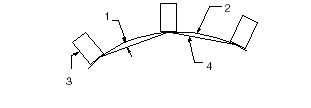
When you set a non-planar retract surface, you can control the maximum deviation of the tool from this surface, as shown in the following illustration, by specifying a Tolerance value in the Retract group box, located on the General tab of the Operation Setup dialog box. The default value is 0.1" (in English units) or 1 mm (in metric units).

Tolerance
Retract surface
Tool
Tool path
See Also